Recommended Practice
for Used FSS Pipe Inspection
STANDARD OPERATING PROCEDURE (SOP 102) — REV 11
The FSS-series of connections are double shouldered rotary shoulder connections with a metal-to-metal seal. It is a hybrid workstring with tubing dimensions and drill pipe durability and strength.
Offline Document Access
All information on this page—including inspection specifications, benchmark diagrams, and dimensional tables—is available as a downloadable PDF.
1. Scope
The following procedure details the recommended delivery conditions for evaluating and qualifying all used tubulars with FSS connections. The procedure specifies the qualification of inspection personnel, a list of required inspection equipment and calibration methods, and a description of required inspection points and acceptance and rejection criteria.
This procedure is not applicable to new tubulars with FSS connections.
2. Normative References
The following documents are fundamental for the use of this document. The latest edition of the listed documents applies:
API Spec 5B: Threading, Gauging, and Inspection of Casing, Tubing, and Line Pipe Threads
API Bull 5T1: Imperfection and Defect Terminology
API Spec 5CT: Casing and Tubing
API Spec 5DP: Drill Pipe
API Spec 7-2: Specification for Threading and Gauging of Rotary Shouldered Thread Connections
RP 5A3 / ISO 13678:2010: Recommended Practice on Thread Compounds for Casing, Tubing, Line Pipe, and Drill Stem Elements
RP 5A5 / ISO 15463:2003: Field Inspection of New Casing, Tubing, and Plain-End Drill Pipe
API RP 5B1: Gauging and Inspection of Casing, Tubing, and Line Pipe Threads
API RP 5C1: Recommended Practice for Care and Use of Casing and Tubing
RP 7G-2: Inspection and Classification of Used Drill Stem Elements
ASNT SNT-TC-1A: Personnel Qualification and Certification in Nondestructive Testing
3. Terms and Definitions
For the purposes of this document, the following terms and definitions apply:
3.1 Conditions
- May: Indicates that a provision is OPTIONAL.
- Should: Indicates that a provision is RECOMMENDED.
- Shall: Indicates that a provision is MANDATORY.
3.2 Physical Characteristics
- Bevel Diameter: The diameter at the intersection of the primary shoulder face and the outside 45° chamfer.
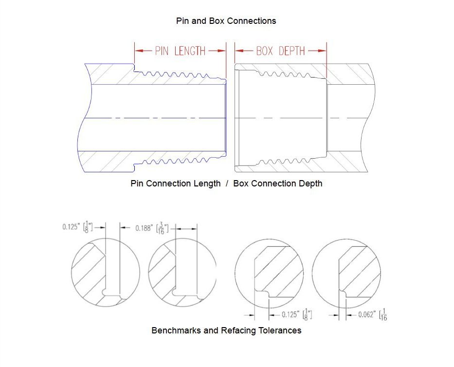
- Bench Mark: The physical characteristic on pin and box connections which allow an inspector to quantify the refacing tolerance. This consists of a turned flat in the box counterbore and on the pin base.
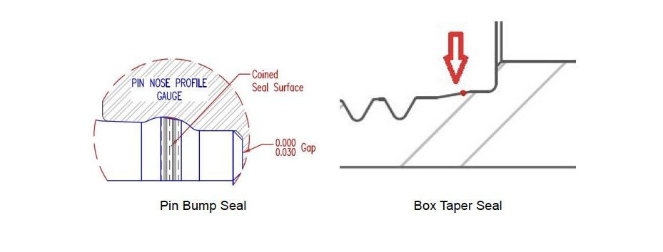
- Bump Seal: The raised metal radiused seal adjacent to the pin nose torque shoulder.
- Cone, Crest: The taper plane parallel to the thread crest.
- Cone, Root: The taper plane parallel to the thread root.
- Cylinder Diameter: The large cylinder diameter near the primary shoulder.
- Lead: The distance from a point on a thread to a corresponding point on the next thread turn, measured parallel to the thread axis, typically in one- or two-inch intervals.
- Pitch Diameter: Diameter of the thread at the mid-point of the untruncated major and minor diameters at a known gauge plane.
- Pitch Diameter Location: A known distance from the primary shoulder face where the PD (pitch diameter) is measured.
- Pilot Nose Diameter: The straight cylindrical diameter between the pin face and thread lead-in chamfer.
- Taper: The increase in the diameter of the connection over a one- or two-inch interval.
- Thread Form / Profile: The shape of the thread in alignment with the axis of the connection and tube.
- Thread Height: The distance from the crest of the thread to root of the thread, measured perpendicular to the pitch line.
- Torque Shoulder, Primary: The torque / sealing shoulder on each connection located closest to the tool joint OD.
- Torque Shoulder, Secondary: The torque / non-sealing shoulder on each connection located closest to the tool joint ID.
4. Drawings
5. Conformance
This section details recommended practices and requirements for use in the inspection, evaluation, and classification of all used tubulars with FSS connections.
5.1 Personnel
All personnel participating in the inspection, maintenance, or service program shall have successfully completed documented, periodic training programs that demonstrate their competence to participate in those programs.
The qualification of inspection personnel shall be the responsibility of the inspection agency and should conform to the requirements of ASNT SNT-TC-1A.
5.2 Equipment, General
All inspection, measuring, and test equipment used in the inspection, maintenance, or service of used FSS connections shall be subject to documented calibration and examination programs that demonstrate each gage’s Certification or Fitness-For-Purpose.
5.3 Equipment, Connections
The equipment listed following is required to inspect used FSS connections:
- 12-inch steel rule (graduated in 1/32nd inch increments minimum)
- 6-inch outside and inside diameter spring calipers
- Digital or dial calipers
- Long stroke depth micrometer (or digital) with setting standard
- Profile template
- Lead gauge with lead gauge standard
- Drift gauge (approximately 12" long; refer to Tables 1 & 2 for exceptions)
- High-intensity flashlight (minimum 500 lux or 50 foot-candles at 3 ft)
- Permanent paint marker
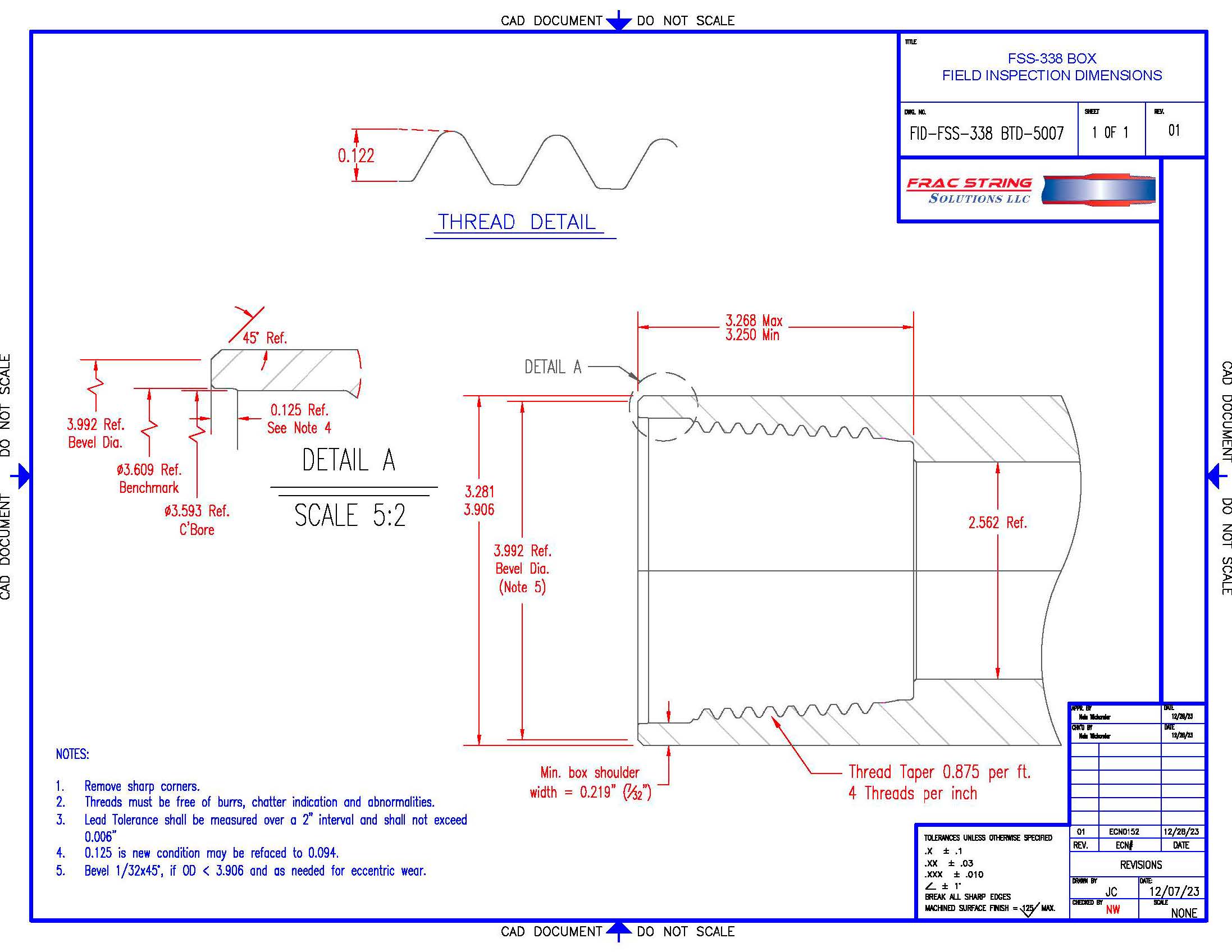
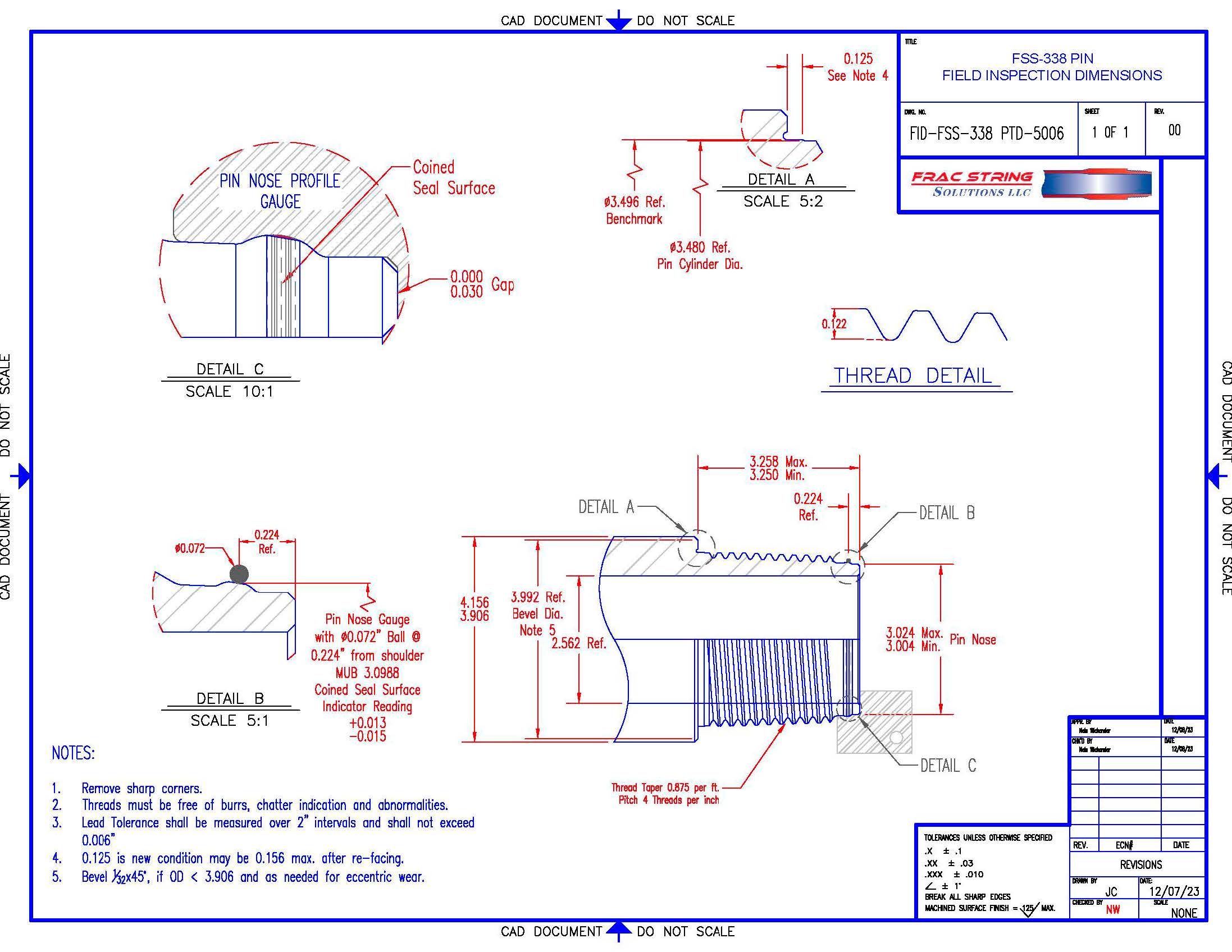
- FSS Connection Field Inspection Dimension Drawing(s)
5.4 Equipment, Tubes
The equipment listed following is recommended to inspect used tubing with FSS connections:
- 4-Way EMI unit with calibration standard
- OD gauge
- Ultrasonic wall thickness gauge
- Pit gauge
- AC hand yoke
5.5 General, Connections and Tubes
The ODs and ID of all tubes / connections should be pressure washed to remove any corrosive compounds or solids that may be found in completion, workover, or fracking fluids to which the tubulars may have been exposed to during use.
Note: In the event the water being used in the pressure washer is filtered and recirculated, it should be periodically checked for salt content.
As reference, the salinity level for fresh water is typically less than 0.5 ppt (parts per thousand), with sea salt water typically measuring at ~34 to 36 ppt. Single- salt completion and workover brines, such as sodium chloride brines, the most common used in the workover industry, can contain 200 ppt or more.
There are three simple and inexpensive methods for measuring salt content in fluids; a handheld refractometer, a hydrometer, and a conductivity meter. The contractor will need to decide which is optimal for their operation.
All used in-bound, rental return, or transfer inspection processes should include a method for testing for H2S exposure. The H2S test program should be scalable, starting at a minimum of five percent (5%) to ten percent (10%) of all joints, increasing to one hundred percent (100%) should any of the five to ten percent (5% to 10%) confirm H2S exposure.
The H2S test compounds are typically a combination of Sodium M Arsenite, Hydrochloric Acid, and distilled water and are commercially available from multiple vendors. H2S test processes usually test for the presence of iron sulphide, which forms when OCTG-grade tubulars are exposed to H2S.
H2S test processes will only inform the owner if the tubulars were exposed to H2S, and not the full detrimental affect the exposure will cause.
Disposition of tubulars exposed to H2S is recommended to be by prior agreement between the pipe vendor and operator.
Rattling is not a recommended cleaning process as it will not remove corrosive compounds or solids that cause rust and scale. Further, FSS connections feature internal upsets and the rattling rollers may not make contact with the tube ID.
All threads and make-up shoulders shall be clean of all thread compound, mud, dirt, or other detritus to allow complete and unimpeded visual and dimensional inspections.
Threads and other sharp or raised edges may be polished using a deburring and finishing wheel. Care shall be taken to avoid contact with the pin nose bump seal and the corresponding box seal contact area.
Note: The 3M Scotch Brite Deburr and Finish Pro Unitized Wheel, PN 90121, is recommended for this process.
The tubes / connections should be sequentially numbered with a paint marker to allow correlation of inspection findings with the inspection report. Where legible, serial numbers shall be documented/ recorded on the inspection report and an owner’s representative notified of the extent of joint traceability.
An abbreviated description of any damage requiring repair or results in rejection should be written on each applicable connection or at the location of the rejection cause.
The use of paint on the connections’ threads, shoulders, or seals as a damage identifier is not recommended as this has a significant risk of causing connection recuts. Color coded bands on the tool joint OD or upset is recommended for damage identification.
Post-inspection, connection threads, seals, and shoulders shall be coated with Jet Lube’s NCS-30 thread compound and protectors installed wrench tight.
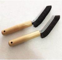
A “Moustache Brush” style brush is recommended (image following), and the NCS-30 thread compound coating should be no more than 1/32nd of an inch thick.
5.6 Visual Inspection, Connections
All connections shall be subject to a Visual Inspection as detailed following.
5.6.1 Primary Make-up Shoulder (External Torque Shoulder)
The shoulder surface should be free of galls, nicks, washes, fins, or other conditions that are deeper than 1/32nd inch or extend across more than 30% of the radial width of the shoulder. If the damage exceeds these limits, the connection shall be refaced.
In general, the refacing repair should only remove sufficient material to repair the damage. A maximum of 1/32nd of an inch of material may be removed during each refacing operation and a maximum of 1/16th of an inch may be removed from the connection before re-threading is required.
After refacing repair, a minimum length of 1/16th of an inch shall remain on the box refacing benchmark, and 3/16ths of an inch maximum shall remain on the pin refacing benchmark.
5.6.2 Secondary Make-up Shoulder (Internal Torque Shoulder)
The Secondary Make-up Shoulder is not a pressure sealing surface, thus general imperfections without raised edges are acceptable. Raised or sharp edges shall be polished.
Cuts, dents, gouges, or scratches that do not exceed 1inch in width are acceptable.
5.6.3 Pin Bump Seal / Box Taper Seal
The pin bump seal and corresponding box taper seal area shall be examined for cuts, galling, or other damage.
Damage may not compromise more than 1/3rd of the sealing surface in the axial direction of the coined area on the pin bump seal or corresponding box taper seal. Any cuts, galling, or other damage that cuts across the coined area of the pin seal should be recut.
The pin bump seal and corresponding box taper seal area may not be reconditioned or otherwise repaired by filing or polishing.
5.6.4 Threads
The stab flank and crest radius of the starting 2 to 3 threads of the pin and box connections commonly round off during normal stabbing operations. This condition is normal and does not affect the service of the connection. The remaining thread flank surfaces shall be free of damage that exceeds 1/16th of an inch in depth or 1/8th of an inch in diameter / width. Any protruding material shall be removed with a round cornered triangle file or by dressing with a soft wheel.
5.6.5 Profile
Thread profile shall be verified along the full length of complete threads in two locations 90 degrees apart. The profile template shall mesh evenly in the threads with less than 1/64th of an inch gaps between the template and the threads.
If the profile template does not mesh in the threads, lead measurements shall be measured over a 1-inch interval and shall not exceed 0.003 inches.
Connections failing the lead inspection shall be further inspected using a Wet Magnetic Particle Inspection method for cracks prior to re-threading.
5.6.6 Hardbanding
When present, the hardbanding shall be inspected for height, cracking, spalling, chipping, flaking and porosity.
If the hardband is worn to less than 1/32nd of an inch above the tool joint OD, it should be marked for reapplication. Differing hardband types should not be overlaid over each other.
If cracking, spalling, chipping, flaking and porosity are found larger than 1/16th of an inch, or smaller than 1/16th of an inch but occurring more than 5 times in any 10 square inch area, the hardband should be considered reject.
5.7 Images - Field Repairable
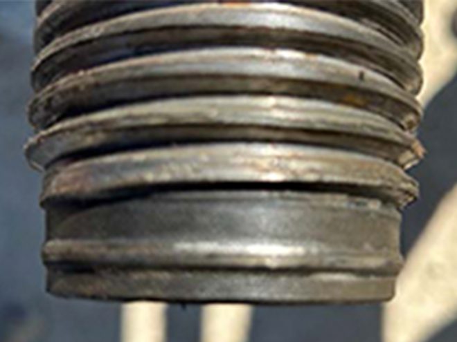
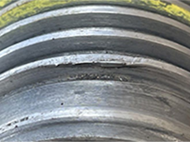
Connections can be brought into compliance by removing raised edges with a
file and/or polishing wheel.
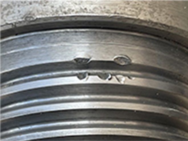
Bring connection into compliance by removing raised edges
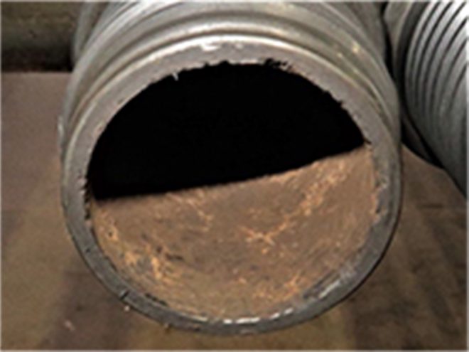
Sharp Corners Must Be Removed
5.8 Images - Rejects
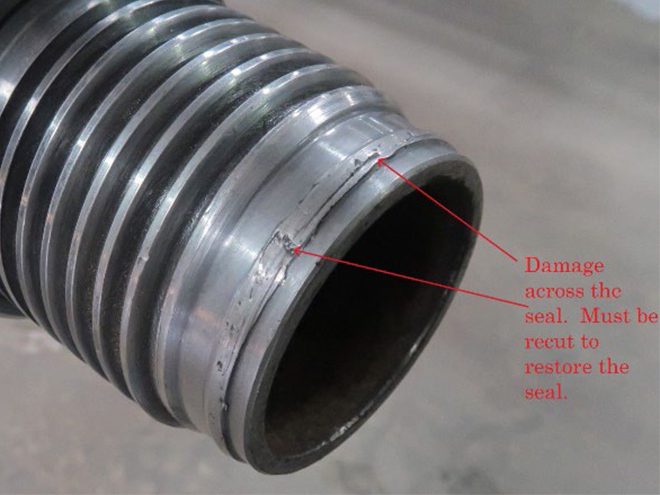
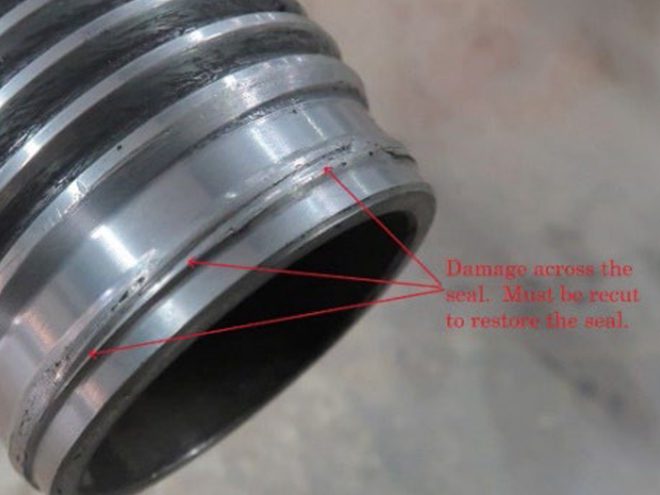
Pin Bump Seal Galling - Not Repairable
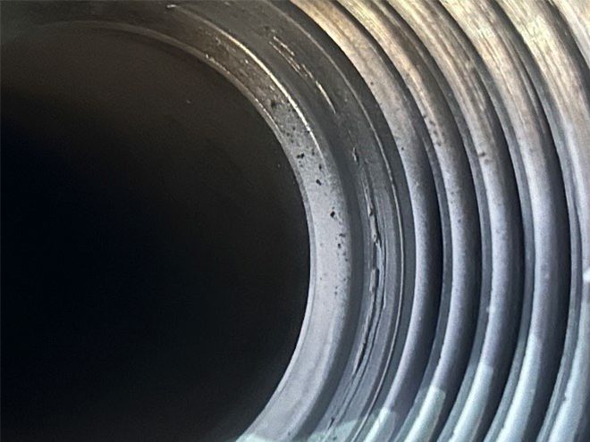
Box seal galled, torque shoulder okay
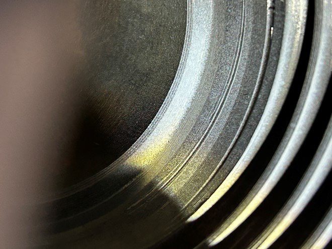
Box seal galled
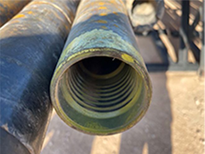
Reject Box Stabbing Damage
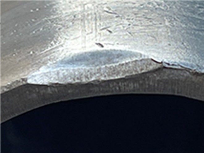
Heavy Mechanical Damage
5.9 Dimensional Inspection, Connections
5.10 Repairs, Connections
In general, out-of-tolerance conditions such as the Box Connection Depth or Pin Connection Length may be repairable via field or shop refacing of one or the other torque shoulders. Care shall be taken to ensure the end result brings the entire connection back into tolerance.
Threads or shoulders reconditioned or repaired by filing, polishing, or refacing shall be phosphate coated. Acceptable substitutions to phosphating include application of a copper sulphate solution.
Note: Vendors and Contractors should be aware that copper-sulfate can provide the level of anti-gall protection phosphate coating will. They should also be aware that failure to fully clean and degrease the area to be treated prior to treatment application will largely negate any benefit whatsoever.
5.10.1 Refacing:
Machine refacing in a CNC lathe or field refacing with an approved refacing procedure and refacing unit that is capable of repairing both external and internal torque shoulders on the same setup. When using a field-type refacing tool, care shall be taken to ensure the thread profile template confirms no raised metal on any thread surfaces can interfere with the alignment of the refacing tool. Post refacing, field or shop, alignment of the primary and secondary torque shoulders to the axis of the pipe must be confirmed. This should be accomplished by measuring the box depth or pin length in several locations 90 degrees apart, with a tolerance of no more than 0.002 inch on all FSS connection sizes. Refacing limits are the same as for repair of damaged shoulders (See Section 4).
5.10.2 Re-threading:
Performance of this operation may not require complete removal of the thread profile if sufficient material can be removed to comply with the new product requirements. However, torque shoulders, seals, and thread elements must be machined to one hundred percent (100%) "new metal". Connections that are recut to "new metal" shall be subject to new connection dimensional tolerances. Recut connections require phosphate coating.
All connections shall be subject to a Dimensional Inspection as listed next. All dimensions shall meet the requirements detailed in Tables 1 and 2.
5.9.1 Box Connection:
- Tool Joint Tong Length
- Tool Joint OD
- Counterbore ID
- Counterbore Wall Thickness
- Connection Depth
- Taper Seal ID (required only if the visual inspection indicates deformation)
5.9.1a Box Specific Requirements:
- The tong length shall be measured from the primary shoulder to the beginning of the hardbanding (if present) or to the beginning of the upset, whichever is shorter.
- Following the use of a straight edge to determine any box swell, the outside diameter of the box shall be measured at a distance of 3/4inch, +/-1/4 of an inch, from the primary make-up shoulder, or at the largest apparent OD.
- If the tubing is inspected to API RP 5C1 requirements, drift length shall be 42 inches. If the tubing is inspected to API RP 7G-2 requirements, drift length shall be minimum of 6" inches but approximately 12" is recommended.
- The wall thickness between the Box OD and Counterbore ID shall be measured around the circumference of the connection to determine minimum counterbore thickness.
- The inside diameter of the box counterbore shall be measured at a distance of 1/4 of an inch from the primary make-up shoulder. Measurements shall be taken around the circumference to determine maximum ID.
- The distance between the primary and secondary make-up shoulders shall be measured in two locations 180 degrees apart.
- The ID of the taper seal shall be measured in two locations 90 degrees apart (required only if the visual inspection indicates deformation).
- Thread roots are to be free of cracks, pits and gouges in the area of the Last Engaged Thread (LET) of the pin or box.
5.9.2 Pin Connection:
- Tool Joint Tong Length
- Tool Joint OD
- Connection Length
- Nose Diameter
- Bump Seal Diameter
5.9.2a Pin Specific Requirements:
- The tong length shall be measured from the primary torque shoulder to the beginning of the hardbanding (if present) or to the beginning of the upset, whichever is shorter.
- The outside diameter of the pin tool joint shall be measured at a distance of 1 inch, +/-1/4 of an inch, from the primary make-up shoulder.
- If the tubing is inspected to API RP 5C1 requirements, drift length shall be 42 inches. If the tubing is inspected to API RP 7G-2 requirements, drift length shall be 6 inches minimum but 12 inches is recommended.
- The distance between the primary and secondary make-up shoulders shall be measured in two locations 180 degrees apart.
- The pin nose diameter shall be measured between the secondary torque shoulder and the bump seal. Measurements shall be taken around the circumference to determine maximum OD (required only if the visual inspection indicates deformation).
- The bump seal diameter shall be measured with the pin nose gauge and conform to the requirements of Column 6, Table 2 (required only if the visual inspection indicates deformation).
- Thread roots are to be free of cracks, pits and gouges in the area of the Last Engaged Thread (LET) of the pin or box.
5.11 Tubes
5.11.1 General
All used in-bound, rental return, or transfer joints should be inspected to API RP5C1, Recommended Practice for Care and Use of Casing and Tubing OR API RP 7G-2, Inspection and Classification of Used Drill Stem Elements requirements, whichever is most acceptable to operators in the region the pipe is used in. Inspection should include the following methodologies:
- Visual Tube for cleanliness, straightness, and other use-induced flaws.
- MPI Slip / Upset for cracks, cuts, pitting, gouges, and other use-induced flaws.
- Full length or end-drift for diameter variations such as crushing or other use-induced flaws.
- OD Gage for diameter variations such as crushing, stretch, or wear.
- UT Wall Thickness for wall loss.
- EMI for longitudinal and transverse cracks, cuts, pitting, gouges, and other use-induced flaws.
All used in-bound, rental return, or transfer inspection processes should also include a method for testing for H2S exposure. The H2S test program should be scalable, starting at a minimum of five percent (5%) to ten percent (10%) of all joints, increasing to one hundred percent (100%) should any of the five to ten percent (5% to 10%) confirm exposure.
The H2S test compounds are typically a combination of Sodium M Arsenite, Hydrochloric Acid, and distilled water and are commercially available from multiple vendors. H2S test processes usually test for the presence of iron sulphide, which forms when OCTG-grade tubulars are exposed to H2S.
H2S test processes will only inform the owner if the tubulars were exposed to H2S, and not the full detrimental affect the H2S exposure will cause.
Disposition of tubulars exposed to H2S is recommended to be by prior agreement between the pipe vendor and operator.
If present, the internal plastic coating (IPC) should be visually inspected for any burned, discolored, or otherwise damaged coating for 3 feet from the face of the pin and box connection.
IPCs should be subjectively graded from 1 to 5, with grade 1 equal to new or no visibly damaged or deteriorated coating and grade 5 equal to fifty percent (>50%) or more of the coating visibly damaged or deteriorated.
Table 1: Used Box Dimensions
| Connection | (1) Tong Length (min) | (2) Tool Joint OD (min/max) | (3) Drift Dia (-0.0, +0.005) | (4) Counterbore Thickness (min) | (5) Counterbore ID (-0.008, +0.015) | (6) Connection Depth (range) | (7) Taper Seal ID (+/-0.005) |
|---|---|---|---|---|---|---|---|
| FSS-247® | 3" | 2.843" / 3.093" | 1.773" | 0.145" | 2.678" | 2.750" to 2.768" | MRP |
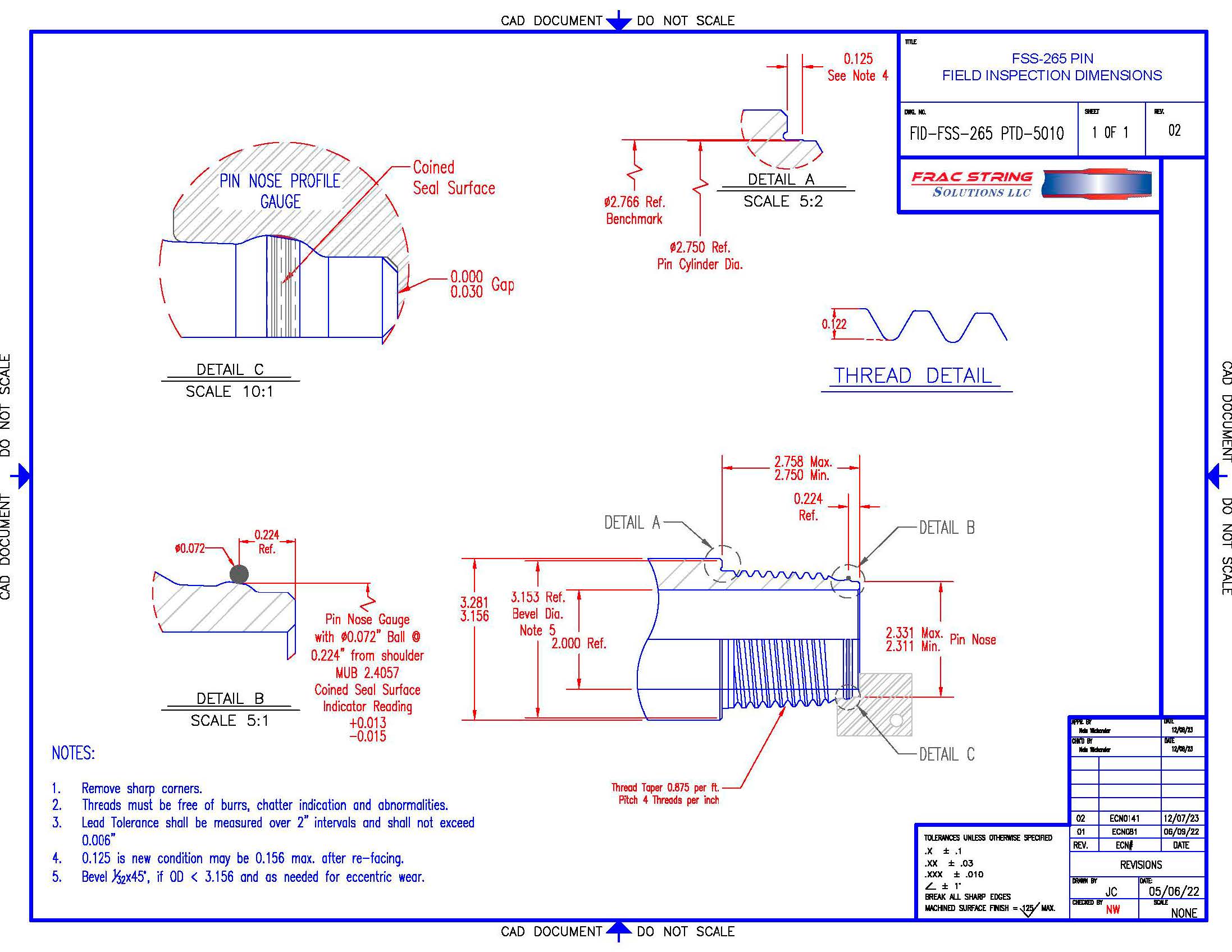
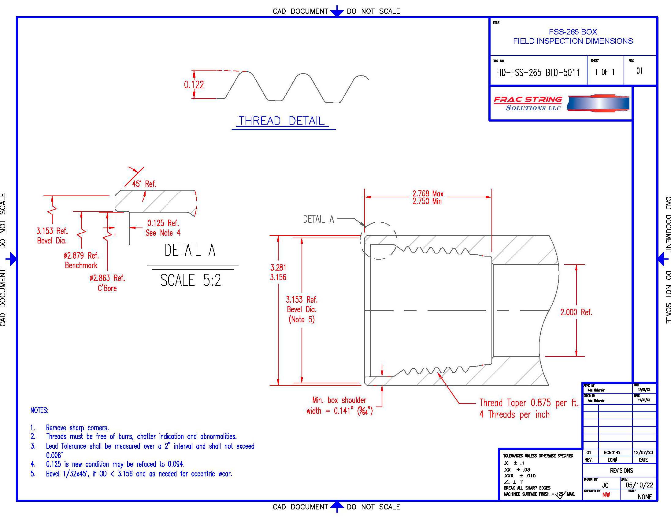
| FSS-265® | 3" | 3.156" / 3.281" | 1.938" | 0.141" | 2.863" | 2.750" to 2.768" | MRP |
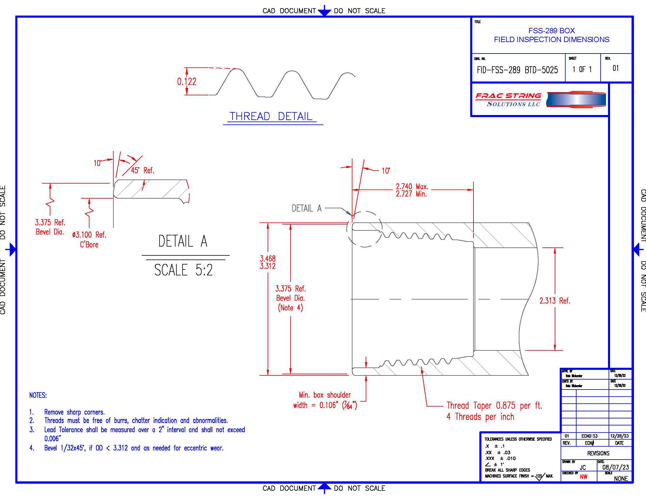
| FSS-289 | 3" | 3.312" / 3.468" | 2.250" | 0.106" | 3.100" | 2.727" to 2.740" | MRP |
| FSS-329 | 3.75" | TBA / 4.031" | 2.438" | TBA | TBA | 3.250" to 3.263" | MRP |
| FSS-338® | 3.75" | 3.906" / 4.156" | 2.500" | 0.219" | 3.593" | 3.250" to 3.263" | MRP |
- The tong length shall be measured from the primary shoulder to the beginning of the hardbanding (if present) or to the beginning of the upset, whichever is shorter.
- Following the use of a straight edge to determine any box swell, the outside diameter of the box shall be measured at a distance of 3/4inch, +/-1/4 of an inch, from the primary make-up shoulder, or at the largest apparent OD. Refer also to 5.10.1.
- If the tubing is inspected to API RP 5C1 requirements, drift length shall be 42 inches. f the tubing is inspected to API RP 7G-2 requirements, drift length shall be 6 inches but FSS recommends approximately 12”.
- The wall thickness between the Box OD and Counterbore ID shall be measured around the circumference of the connection to determine minimum counterbore thickness.
- The inside diameter of the box counterbore shall be measured at a distance of ¼ of an inch from the primary makeup shoulder. Measurements shall be taken around the circumference to determine maximum ID.
- The distance between the primary and secondary make-up shoulders shall be measured in two locations 180 degrees apart.
- The ID of the taper seal shall be measured in two locations 90 degrees apart (required only if the visual inspection indicates deformation).
Table 2: Used Pin Dimensions
| Connection | (1) Tool Joint Tong Lenth (min) | (2) Tool Joint OD (min) | (3) Drift Diameter (-0.0, +0.005) | (4) Connection Length (-0, +0.008) | (5) Nose Diameter (range) | (6) Bump Seal Diameter (+0.013/-0.015) |
|---|---|---|---|---|---|---|
| FSS-247® | 0.500" | 2.843" | 1.773" | 2.750" | 2.126" to 2.146" | Pin Nose Gauge |
| FSS-265® | 0.500" | 3.156" | 1.938" | 2.750" | 2.311" to 2.331" | Pin Nose Gauge |
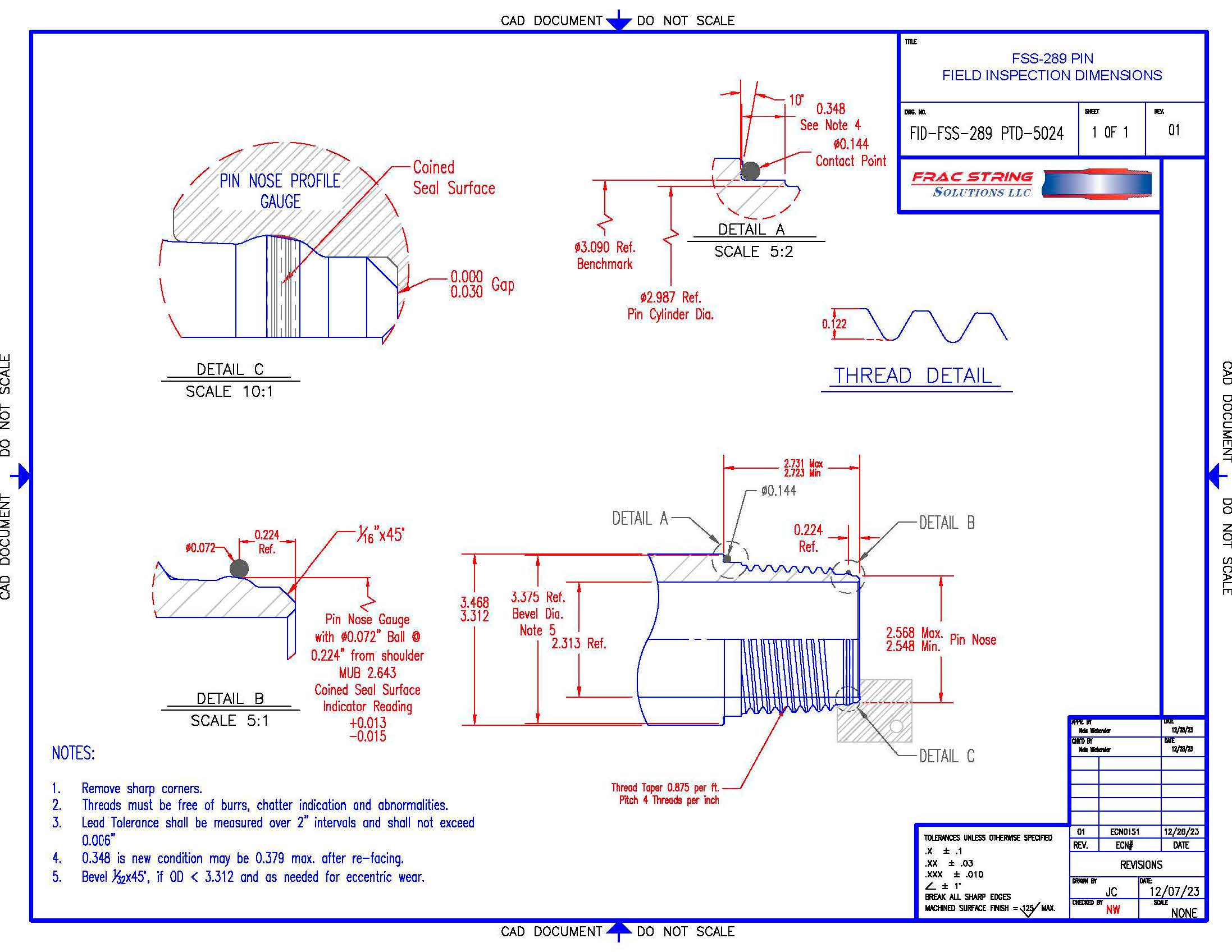
| FSS-289 | 0.500" | 3.312" | 2.250" | 2.723"(a) | 2.548" to 2.568" | Pin Nose Gauge |
| FSS-329 | TBA | TBA | 2.438" | TBA | TBA | Pin Nose Gauge |
| FSS-338® | 0.500" | 3.906" | 2.500" | 3.250" | 3.004" to 3.024" | Pin Nose Gauge |
| (a) The FSS-289 pin connection length measurement shall be made with 0.144" ball diameter contact point. All other connection sizes may use any size or type of contact point. | ||||||
- The tong length shall be measured from the primary torque shoulder to the beginning of the hardbanding (if present) or to the beginning of the upset, whichever is shorter.
- The outside diameter of the pin tool joint shall be measured at a distance of 1 inch, +/-1/4 of an inch, from the primary make-up shoulder. Refer also to 5.10.1.
- If the tubing is inspected to API RP 5C1 requirements, drift length shall be 42 inches long. If the tubing is inspected to API RP 7G-2 requirements, drift length shall be 6 inches long.
- The distance between the primary and secondary make-up shoulders shall be measured in two locations 180 degrees apart.
- The pin nose diameter shall be measured between the secondary torque shoulder and the bump seal. Measurements shall be taken around the circumference to determine range compliance.
- The bump seal diameter shall be measured with the pin nose gauge and conform the requirements of Column 6, Table 2. (4) (a) The FSS-289 pin connection length measurement shall be made with 0.144” ball diameter contact point. All other connection sizes may use any size or type of contact point.
Table 3: API RP 5C1 Used Tube Inspection Summary
API RP5C1 - Recommended Practice for Care and Use of Casing and Tubing
Table 4 - Inspection Process Requirements
Classification and Color Coding of Used Casing and Tubing
| (1) Class | (2) Color Band | (3) Percent Loss of Nominal Wall Thickness | (4) Minimum Percent Remaining Wall Thickness |
|---|---|---|---|
| 2 | Yellow | 0 to 15% | 85% |
| 3 | Blue | 16% to 30% | 70% |
| 4 | Green | 31% to 50% | 50% |
| 5 | Red | Over 50% | Less than 50% |
All used in-bound, rental return, or transfer inspection processes should also include a method for testing for H2S exposure. The H2S test program should be scalable, starting at a minimum of five percent (5%) to ten percent (10%) of all joints, increasing to one hundred percent (100%) should any of the five to ten percent (5% to 10%) confirm exposure.
The H2S test compounds are typically a combination of Sodium M Arsenite, Hydrochloric Acid, and distilled water and are commercially available from multiple vendors. H2S test processes usually test for the presence of iron sulphide, which forms when OCTG-grade tubulars are exposed to H2S.
The processes will only inform the owner if the tubulars were exposed to H2S, and not the full detrimental affect the H2S exposure will cause.
Disposition of tubulars exposed to H2S is recommended to be by prior agreement between the pipe vendor and operator.
Table 4: API RP 7G-2 Used Tube Inspection Summary
API RP 7G-2 — Inspection and Classification of Used Drill Stem
Table B.15, Used Work String Tubing — Inspection Process Requirements
| (1) Inspection Level | (2) Full Length Visual | (3) OD Guage | (4) UT Wall Measurement | (5) EMI Full Length | (6) Full Length Drift | (7) MPI Slip Area | (8) Connection Inspection |
|---|---|---|---|---|---|---|---|
| Standard | Req'd | Req'd | Req'd | Req'd | Req'd | Req'd | Req'd |
| Moderate | Req'd | Req'd | Req'd | Req'd | Req'd | Req'd | Req'd |
| Critical | Req'd | Req'd | Full Length UT: L, T, & WT | Req'd | Req'd | Req'd | Req'd |
All used in-bound, rental return, or transfer inspection processes should also include a method for testing for H2S exposure. The H2S test program should be scalable, starting at a minimum of five percent (5%) to ten percent (10%) of all joints, increasing to one hundred percent (100%) should any of the five to ten percent (5% to 10%) confirm exposure.
The H2S test compounds are typically a combination of Sodium M Arsenite, Hydrochloric Acid, and distilled water and are commercially available from multiple vendors. H2S test processes usually test for the presence of iron sulphide, which forms when OCTG-grade tubulars are exposed to H2S.
The processes will only inform the owner if the tubulars were exposed to H2S, and not the full detrimental affect the H2S exposure will cause.
Disposition of tubulars exposed to H2S is recommended to be by prior agreement between the pipe vendor and operator.
Table 5 - API RP 7G-2 Used Tube Classifacation
API RP 7G-2 — Inspection and Classification of Used Drill Stem
Table B.15, Used Work String Tubing — Inspection Process Requirements
Exterior
| (1) Flaw Type | (2) Premium (two white bands) | (3) Premium (two white bands) | (4) Class 2 (one yellow band) | (5) Class 3 (one orange band) |
|---|---|---|---|---|
| OD Wear Dents / Mashes Crushing / Necking | RBW > 87.5% OD > 98% OD > 98% | RBW > 80% OD > 97% OD > 97% | RBW > 70% OD > 96% OD > 96% | RBW >70% OD >96% OD >96% |
| SA Cuts / Gouges | Depth ≤ 10% of ABW | Depth ≤ 10% of ABW | Depth 20% of ABW | Depth > 20% of ABW |
| Stretching String Shot | OD > 98% OD < 102% | OD > 97% OD < 103% | OD > 96% OD < 104% | OD > 96% OD < 104% |
| Ext. Corrosion | RBW > 87.5% | RBW > 80% | RBW > 70% | RBW > 70% |
| Long. Cuts / Gouges | RBW > 87.5% | RBW > 80% | RBW > 70% | RBW > 70% |
| Trans. Cuts / Gouges Cracls | RBW > 87.5% None | RBW > 80% None | RBW > 80% None | RBW > 80% None |
Interior
| (1) Flaw Type | (2) Premium (two white bands) | (3) Premium (two white bands) | (4) Class 2 (one yellow band) | (5) Class 3 (one orange band) |
|---|---|---|---|---|
| Corrosion | RBW > 87.5% | RBW > 80% | RBW > 70% | RBW > 70% |
Erosion | RBW > 87.5% | RBW > 80% | RBW > 70% | RBW > 70% |
| Drift(a) | < 0.032" Nom TJ ID | < 0.032" Nom TJ ID | < 0.032" Nom TJ ID | < 0.032" Nom TJ ID |
Cracks | None | None | None | None |
a) See Table 1 or Table 2 for FSS drift diameters.
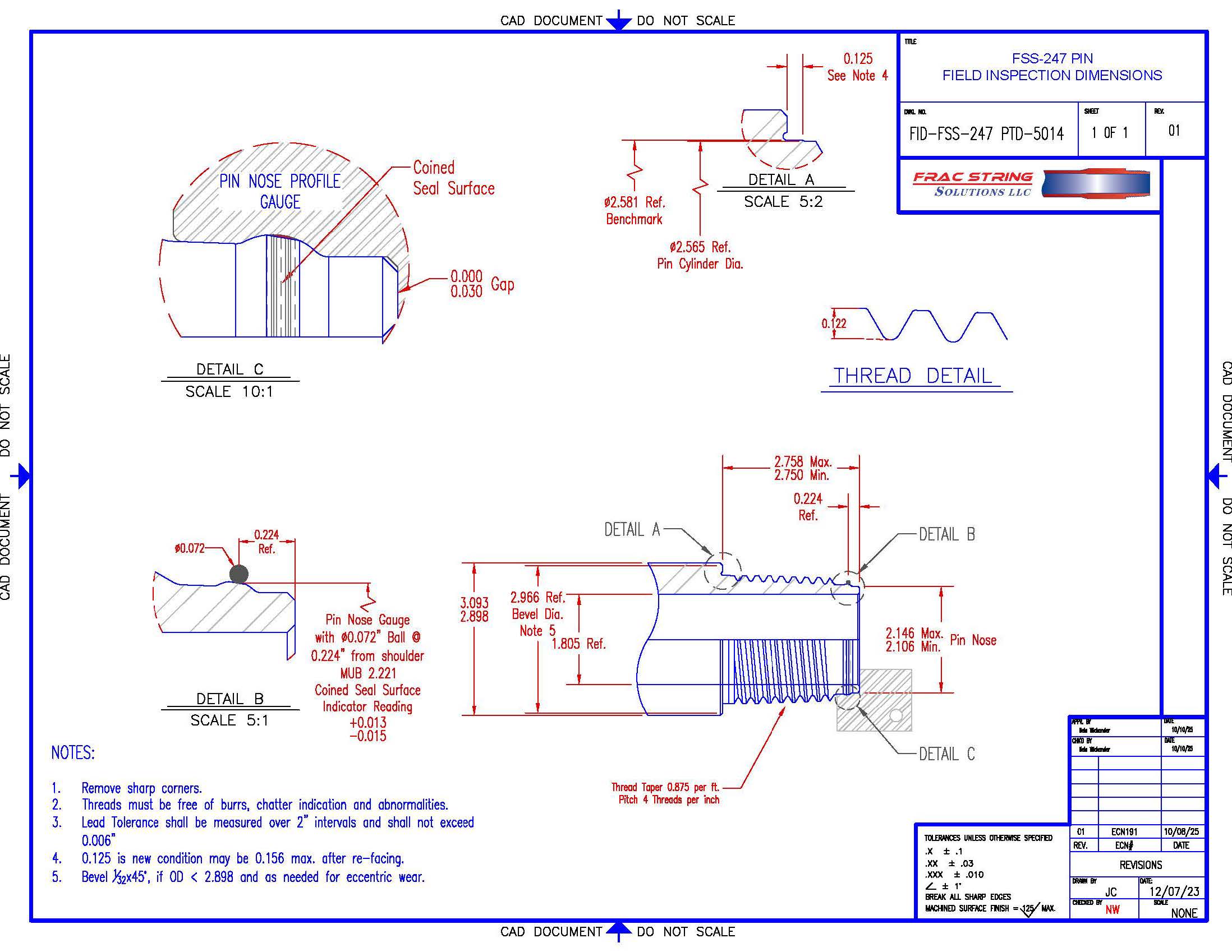
Field Inspection Drawing, FSS-247® Pin
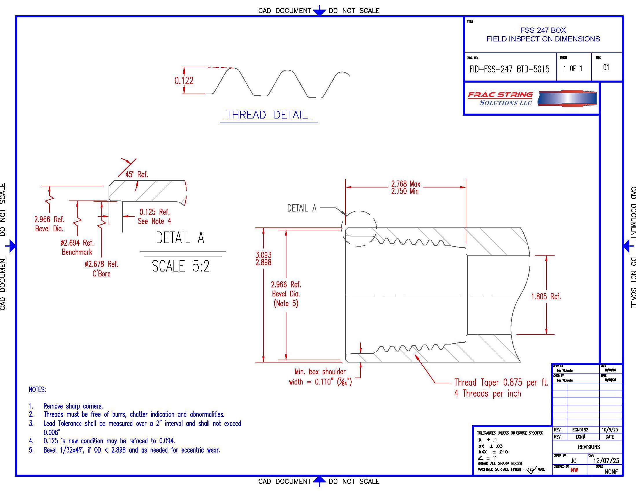
Field Inspection Drawing, FSS-247® Box
Field Inspection Drawing, FSS-265® Pin
Field Inspection Drawing, FSS-265® Box
Field Inspection Drawing, FSS-289 Pin
Field Inspection Drawing, FSS-289 Box
Field Inspection Drawing, FSS-338® Pin
Field Inspection Drawing, FSS-338® Box